Look ma, no Arduino! (μControl 101)
After playing with Arduino for a few projects and watching a motivational video by way of a demonseed edu kit, I wanted to return to a beginner project (a remote controlled car) without depending on the affordances of an Arduino-like board.
I decided to use an ATTiny85 providing a 16.5MHz clockspeed, 5 i/o signal pins and allowing 8192 bytes of program instructions, 512 bytes of eeprom (static) memory and 2096 bytes of flash memory.
Bootstrapping a microprocessor
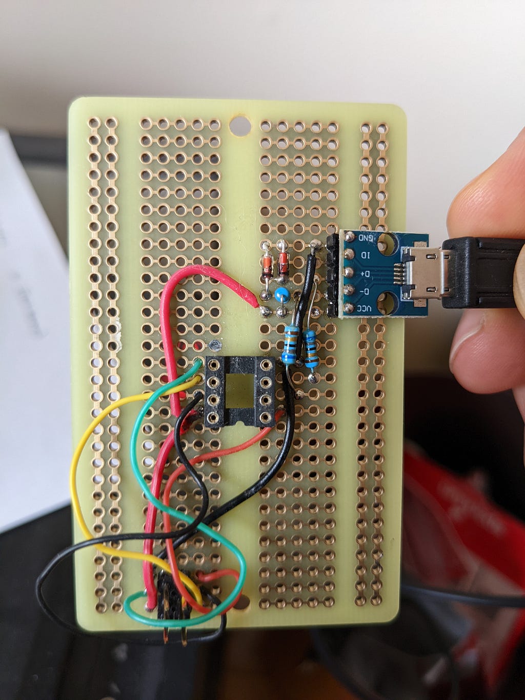
Getting instructions onto the microprocessor initially requires using a dongle (which uses another microprocessor!) to flash a bootloader onto the microprocessor. These are the instructions the processor runs when powered on. Following the instructions provided by @MG, I flashed a bootloader that allowed me to directly program the chip via USB. After flashing the bootloader and installing “Digispark” Arduino Board support, I’m able to upload code from the Arduino IDE using the following rigging:
Driving the motors
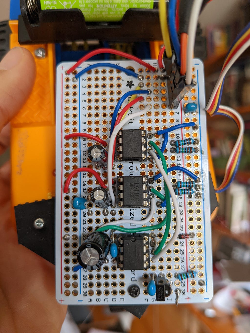
My car has three wheels, two of which are powered and must be able to independently go backwards and forwards in order for the vehicle to turn. I decided to use an H-bridge in a DIP package, instead of going down the rabbit hole of building one from scratch. At first, the program would hang whenever the motors started, as they were drawing all available power from the battery. This was fixed by pairing each of the ICs with a sizeable capacitor.
Remote controlling and Debugging
I used a Roku remote and an IR sensor on the car to relay controls to the microprocessor. The IR sensor connects to pin 2 on the ATTiny, and will read high or low as the signal pulses. The program monitors for IR pulses, and attempts to match against known sequences stored in flash memory.
What are the sequences though? It depends on the period between each sample, which is variable with what else is being done in our run loop. I ended up adding a UART driver to the program to report the observed values via serial. Since I only have 5 signal pins, I added a “debug” mode that uses the pins that usually inform the left motor correction for RX/TX. In non-debug mode, we do the same work (so that the signal matches), but set RX/TX to a non-existing pin.
Demonstration
Learnings
I’m glad to have had a chance to play without the scaffolding of an Arduino-like platform. If I were to re-build this, I would add the USB reprogramming circuit onto the car itself to avoid having to re-seat the IC for every programming cycle. Also, I ended up frying a two ATTinys by plugging them in upside down — hardwiring the USB connections would prevent this.
The shortage of pins and inability to debug with full device functionality is also something I’d avoid — having an interactive debugger is clutch, especially as a beginner. The default failure state is “microcontroller is not doing anything,” whether that’s from using too much memory, a drop in input voltage, divide by zero or hardware failure. If you have been softened by rich stack traces and interactive debuggers, this will require some adjustment.